 |
|
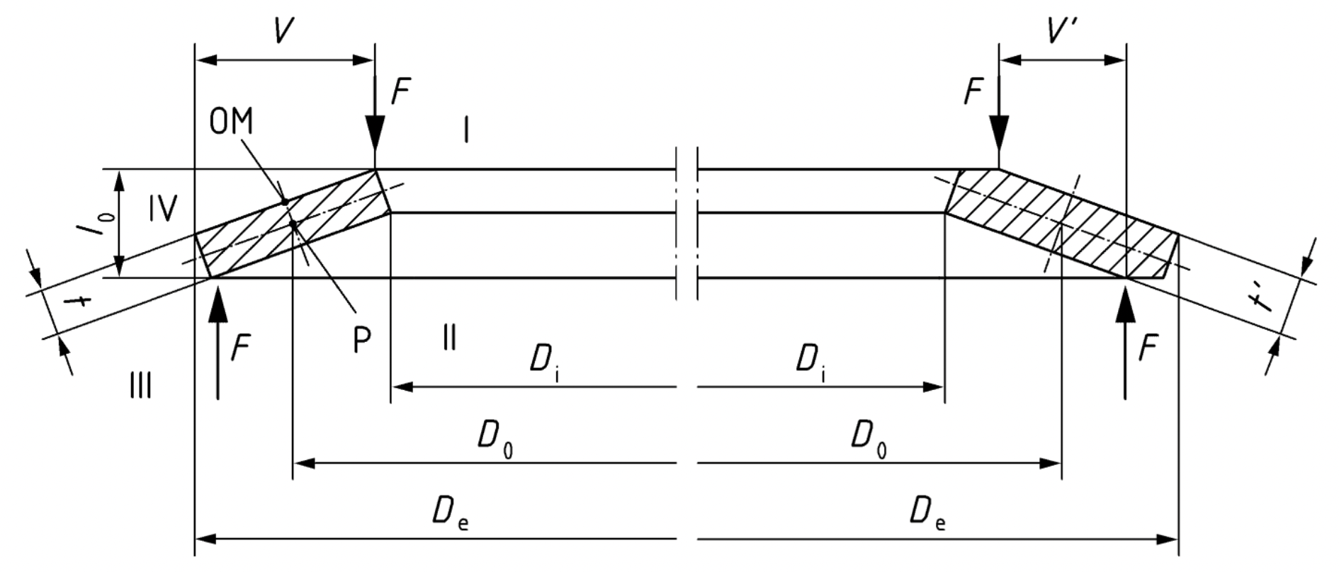
| a) without flat bearings: | b) with flat bearings: |
| Group 1 | Group 3 |
| Group 2 | |
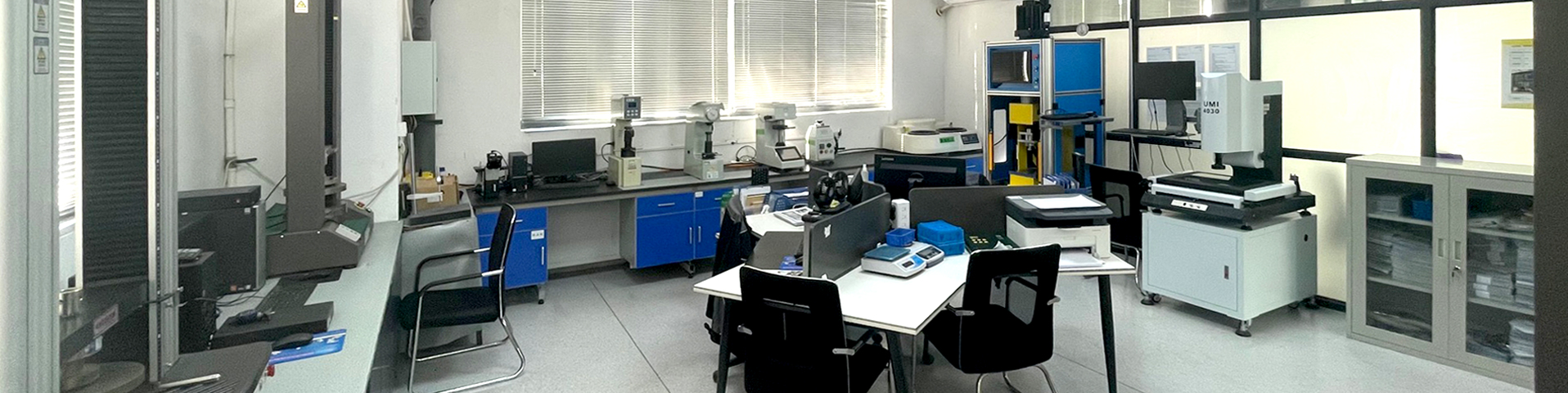
| Group | t |
With flat bearings and reduced thickness |
| 1 | <1.25 | No |
| 2 | 1.25 ≤ t ≤6 | No |
| 3 | 6≤ t ≤ 14 | Yes |
| Series | h0/t | |
| A | ~0.40 | |
| B | ~0.75 | |
| C | ~0.1.3 |
| De or Di mm | Permissible deviation in mm | ||
| De | Di | Concentricity | |
| over 3 to 6 | 0 / -0.12 | +0.12 / 0 | 0.15 |
| over 6 to 10 | 0 / -0.15 | +0.15 / 0 | 0.18 |
| over 10 to 18 | 0 / -0.18 | +0.18 / 0 | 0.22 |
| over 18 to 30 | 0 / -0.21 | +0.21 / 0 | 0.26 |
| over 30 to 50 | 0 / -0.25 | +0.25 / 0 | 0.32 |
| over 50 to 80 | 0 / -0.30 | +0.30 / 0 | 0.60 |
| over 80 to 120 | 0 / -0.35 | +0.35 / 0 | 0.70 |
| over 120 to 180 | 0 / -0.40 | +0.40 / 0 | 0.80 |
| over 180 to 250 | 0 / -0.46 | +0.46 / 0 | 0.92 |
| over 250 to 315 | 0 / -0.52 | +0.52 / 0 | 1.04 |
| over 315 to 400 | 0 / -0.57 | +0.57 / 0 | 1.14 |
| over 400 to 500 | 0 / -0.63 | +0.63 / 0 | 1.26 |
| t mm | Tolerance for l0 mm | |
| Group 1 | < 1.25 | +0.10 / -0.05 |
| Group 2 | 1.25 to 2.0 | +0.15 / -0.08 |
| > 2.0 to 3.0 | +0.20 / -0.10 | |
| > 3.0 to 6.0 | +0.30 / -0.15 | |
| Group 3 | > 6.0 to 16.0 | +0.30 / -0.30 |
| To ensure the specified spring forces ,DIN16983 allows the overall height tolerance to be slightly exceeded. | ||
| t or t' mm | Tolerance for t mm | |
| Group 1 | 0.2 to 0.6 | +0.02 / -0.06 |
| > 0.6 to < 1.25 | +0.03 / -0.09 | |
| Group 2 | 1.25 to 3.8 | +0.04 / -0.12 |
| > 3.8 to 6.0 | +0.05 / -0.15 | |
| Group 3 | > 6.0 to 16.0 | +0.10 / -0.10 |
| t or t' mm | Tolerance for F at the test length lp=l0-0.75h0 | |
| Group 1 | < 1.25 | +25% / -7.5% |
| Group 2 | 1.25 to 3.0 | +15% / -7.5% |
| > 3.0 to 6.0 | +10% / -5.0% | |
| Group 3 | > 6.0 to 16.0 | +5.0% / -5.0% |
| De or Di | Total clearance |
| Up to 16 | 0.2 |
| Over 16 up to 20 | 0.3 |
| Over 20 up to 26 | 0.4 |
| Over 26 up to 31.5 | 0.5 |
| Over 31.5 up to 50 | 0.6 |
| Over 50 up to 80 | 0.8 |
| Over 80 up to 140 | 1.0 |
| Over 140 up to 250 | 1.6 |
| Where possible, the guiding element and the support plate shall be made from case hardened materials, with a case depth of ≈ 0,8 mm, and have a minimum hardness of 60 HRC. The surface of the guiding element should be smooth and perfectly finished. It shall be permitted to use unhardened guiding elements where the disc spring is subject to static loading. |
| Forces and Deflections in spring stack | Forces * | Deflections | Combinations |
| Single spring | 1 times | 1 times | 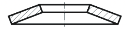 |
| 2P = 2 springs in Parallel | 2 times | 1 times |  |
| 3S = 3 springs in series | 1 times | 3 times | 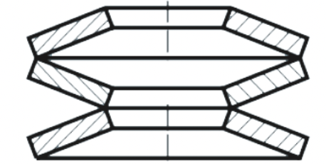 |
| 2P3S = 2 springs in Parallel, 3 Parallel sets in Series | 2 times | 3 times | 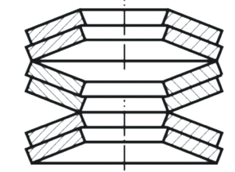 |
| * Considering the friction, the spring stack actual forces from loading and unloading may deviated from the figures calcualted | |||
| Materials Datasheet |
| Corrosion Protective |
| Tolerance |